555 Timer Schematic - The 555 timer ic is an integrated circuit (chip) used in a variety of timer, delay, pulse generation, and oscillator applications.
byAdmin•
0
555 Timer Schematic - The 555 timer ic is an integrated circuit (chip) used in a variety of timer, delay, pulse generation, and oscillator applications.. 555 timer helpers schematic adding of a resistor and capacitor to the trigger will not work for very short trigger or output pulses because there is a rc delay in the decay and recovery of the voltage at the trigger. We can use the 555 as a timer for up to 10 minutes. Derivatives provide two (556) or four (558) timing circuits in one package. The 555 timer ic is an integrated circuit (chip) used in a variety of timer, delay, pulse generation, and oscillator applications. For a stable operation as an oscillator , the
Simple ne555 ic tester circuit diagram. Working and schematic diagram of clap swith circuit In 2017, it was said over a billion 555 timers are pr. If you want to know all the pinout of the 555 timer, what each pin is and what each pin does, see 555 timer pinout. For a stable operation as an oscillator , the
FM Generation using 555 Timer from electrosome.com Derivatives provide two (556) or four (558) timing circuits in one package. 1 by forrest mims is a great resource to have on your bench. Apr 15, 2020 · people know it as the 555 timer ic. If you want to know all the pinout of the 555 timer, what each pin is and what each pin does, see 555 timer pinout. Working and schematic diagram of clap swith circuit Mar 08, 2021 · if you want to learn more about the 555 timer, the book timer, op amp, and optoelectronic circuits and projects book vol. Simple ne555 ic tester circuit diagram. You can watch how each of the circuits in this tutorial work in this video:
In this circuit, we will connect the 555 timer to be in astable mode.
Apr 15, 2020 · people know it as the 555 timer ic. The 555 timer can be obtained very cheaply from pretty much any electronic retailer. If you want to know all the pinout of the 555 timer, what each pin is and what each pin does, see 555 timer pinout. I have used two 555 timer ics in this project and both these 555 ics act as astable multivibrators. Mar 08, 2021 · if you want to learn more about the 555 timer, the book timer, op amp, and optoelectronic circuits and projects book vol. The simplicity of the timer, in conjunction with its ability to produce long time delays in a variety of applications, has lured many designers from mechanical timers, op amps, and various discrete circuits into the ever increasing ranks of timer users. 555 timer helpers schematic adding of a resistor and capacitor to the trigger will not work for very short trigger or output pulses because there is a rc delay in the decay and recovery of the voltage at the trigger. In this circuit, we will connect the 555 timer to be in astable mode. In other words, 555 timer is a circuit which may be connected as a stable or monostable multivibrator. Oct 13, 2018 · the 555 timer ic is an integrated circuit used in a variety of timer, pulse generation and oscillator applications. Derivatives provide two (556) or four (558) timing circuits in one package. In the time delay mode of operation, the time is precisely controlled by one external resistor and capacitor. It was commercialized in 1972 by signetics.
555 timer helpers schematic adding of a resistor and capacitor to the trigger will not work for very short trigger or output pulses because there is a rc delay in the decay and recovery of the voltage at the trigger. If you want to know all the pinout of the 555 timer, what each pin is and what each pin does, see 555 timer pinout. 1 by forrest mims is a great resource to have on your bench. Learn by doing is the best. Simple ne555 ic tester circuit diagram.
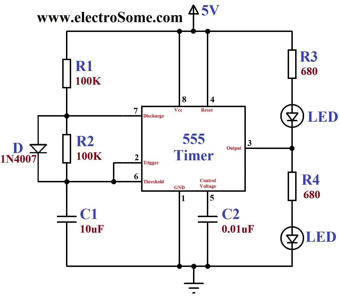
Dancing Light using 555 Timer from electrosome.com Mar 08, 2021 · if you want to learn more about the 555 timer, the book timer, op amp, and optoelectronic circuits and projects book vol. The 555 timer can be obtained very cheaply from pretty much any electronic retailer. The book has lots of information about the 555 timer, opamps, and other ic's too. I have used two 555 timer ics in this project and both these 555 ics act as astable multivibrators. Apr 15, 2020 · people know it as the 555 timer ic. Working and schematic diagram of clap swith circuit If you want to know all the pinout of the 555 timer, what each pin is and what each pin does, see 555 timer pinout. The 555 timer ic is an integrated circuit (chip) used in a variety of timer, delay, pulse generation, and oscillator applications.
You can watch how each of the circuits in this tutorial work in this video:
Derivatives provide two (556) or four (558) timing circuits in one package. This circuit is also called a delay. In other words, 555 timer is a circuit which may be connected as a stable or monostable multivibrator. I have used two 555 timer ics in this project and both these 555 ics act as astable multivibrators. The 555 timer ic is an integrated circuit (chip) used in a variety of timer, delay, pulse generation, and oscillator applications. Working and schematic diagram of clap swith circuit The book has lots of information about the 555 timer, opamps, and other ic's too. For a stable operation as an oscillator , the Oct 13, 2018 · the 555 timer ic is an integrated circuit used in a variety of timer, pulse generation and oscillator applications. Mar 08, 2021 · if you want to learn more about the 555 timer, the book timer, op amp, and optoelectronic circuits and projects book vol. The simplicity of the timer, in conjunction with its ability to produce long time delays in a variety of applications, has lured many designers from mechanical timers, op amps, and various discrete circuits into the ever increasing ranks of timer users. The 555 timer can be obtained very cheaply from pretty much any electronic retailer. We can use the 555 as a timer for up to 10 minutes.
In 2017, it was said over a billion 555 timers are pr. It was commercialized in 1972 by signetics. Mar 08, 2021 · if you want to learn more about the 555 timer, the book timer, op amp, and optoelectronic circuits and projects book vol. The 555 timer can be obtained very cheaply from pretty much any electronic retailer. Oct 13, 2018 · the 555 timer ic is an integrated circuit used in a variety of timer, pulse generation and oscillator applications.
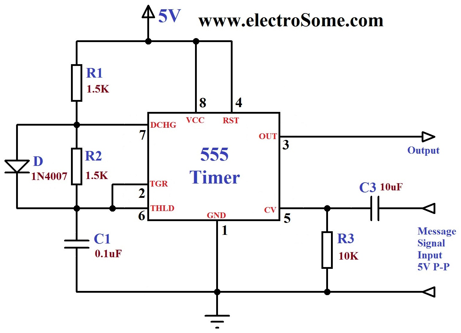
ECEN 2250, myDAQ Experiment 1: Capacitors and the 555 Timer from ecee.colorado.edu Mar 08, 2021 · if you want to learn more about the 555 timer, the book timer, op amp, and optoelectronic circuits and projects book vol. In 2017, it was said over a billion 555 timers are pr. You can watch how each of the circuits in this tutorial work in this video: In the time delay mode of operation, the time is precisely controlled by one external resistor and capacitor. This circuit is also called a delay. In more simple words, 555 timer is a monolithic timing circuit, which can produce accurate timing pulses with 50% or 100% duty cycle. 555 timer is a digital monolithic integrated circuit (ic) which may be used as a clock generator. The 555 timer ic is an integrated circuit (chip) used in a variety of timer, delay, pulse generation, and oscillator applications.
555 timer is a digital monolithic integrated circuit (ic) which may be used as a clock generator.
The 555 timer can be obtained very cheaply from pretty much any electronic retailer. It was commercialized in 1972 by signetics. Apr 15, 2020 · people know it as the 555 timer ic. This circuit is also called a delay. Simple ne555 ic tester circuit diagram. Learn by doing is the best. 555 timer helpers schematic adding of a resistor and capacitor to the trigger will not work for very short trigger or output pulses because there is a rc delay in the decay and recovery of the voltage at the trigger. Description the 555 timer consists of two voltage comparators, a bistable 555 timer is a digital monolithic integrated circuit (ic) which may be used as a clock generator. If you want to know all the pinout of the 555 timer, what each pin is and what each pin does, see 555 timer pinout. The simplicity of the timer, in conjunction with its ability to produce long time delays in a variety of applications, has lured many designers from mechanical timers, op amps, and various discrete circuits into the ever increasing ranks of timer users. Working and schematic diagram of clap swith circuit I have used two 555 timer ics in this project and both these 555 ics act as astable multivibrators.